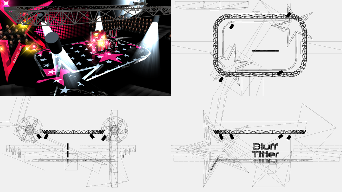
Camera layer

The above screenshot shows 4 camera layers, 1 perspective and 3 parallel. The template used is from BixPack 1.

What can I do with the camera layer?
With the camera layer you can create a view to your scene. A show needs at least 1 camera layer.
How do I add a camera layer?
Choose LAYER > Add layer > Add camera layer... to add a new camera layer.
The new camera layer can be selected from the layers dropdown to make it the active layer.
Examples
The installer comes with shows demonstrating the possibilities of the camera layer. Choose FILE > Open show... and select a show from the BluffTitler/Media/Shows/Camera folder.
To quickly switch between your own shows and the ones that came with the installer, click on the Personal and App buttons in the upper right corner of the file dialog.

Camera layers and viewports
Every time you add a camera layer, a viewport is added. Every viewport has its own camera layer with its own settings and keyframe animation. You can create as many camera layers as you want, but BluffTitler renders a maximum of 4 viewports at the same time. You can temporarily hide a viewport by unmarking the Visible checkbox of the corresponding camera layer.

Extra info when editing
By pressing <F2> or choosing SETTINGS > Render info you can show/hide extra information including the camera coordinate system in the lower left corner, the local coordinate system of the active layer, the crosshair in the centre and the safe. This information is automatically hidden when exporting to picture or video.
For example you can visualise the position and rotation of the camera layer (or any other layer) by making it the active layer and pressing <F2>.
Positioning the camera
Moving and rotating the camera works best with your mouse. Learn more
Tone mapping
Use the Brightness and Gamma properties to change the dynamic range.
The active viewport
Next to using the Layers dropdown, you can select a camera layer by double clicking on its viewport. Make sure not to click on a layer because this way, the layer will be selected instead. The active viewport can be identified by pressing <F2>.
Attaching a new layer to an existing camera
Make the camera layer the active layer before creating the new layer.
Attaching an existing layer to an existing camera
Choose LAYER > Attach layer > Attach active layer.
Post-processing
When an effect is applied to the camera layer, the render output is used as the 1st texture. This way the effect can be used as a post-processing effect.
Effects specifically designed for use in the camera layer can be found in the Camera folder. The effects in the Filters folder also work great applied to the camera layer.

Blur
Apply the Camera/Blur effect to blur the whole screen.

Depth of field (DOF)
Apply the Camera/CameraDepthOfField effect to make the blur depend on the distance to the camera.
With the FX DOF range property you can set the depth range (DOF) that appears sharp. A large range creates a deep focus, a small range a shallow focus.
The FX DOF blur property controls the amount of out of focus outside this range.

Halftones
This example uses the Filters/Halftones effect.

Swirl
This example uses the Filters/Swirl effect.
Many more effects are available. Have fun experimenting!

Distortion
This example uses the Filters/Distortion effect.
It can be used to simulate decoding/encoding bugs and connection errors.
Glow

Glow
Mark the Glow checkbox in the LAYER > Active layer properties... dialog to glow a layer. Control the glow with the glow properties of the camera layer.

Outline
Set the Glow intensity property to a negative value to render the glow behind the layer. This can be used to create an outline.
Simulate LED screens
Camera layer style 1

Perspective projection
In this projection, objects that are further away from the camera are rendered smaller. Use the Field of view property to zoom in and out.

Parallel projection
This projection is called parallel because parallel lines remain parallel. The size of the objects is independent of their distance to the camera. Use the Size property to set the global size of all objects. This projection is also called orthographic.
Camera layer style 2

Solid
Normal view

Wireframe
All layers are rendered as wireframes
Camera layer style 3
Render all
This style renders everything.
Render back
This style only renders layers in the background, for example a picture layer using the Fullscreen in background style.
Render 3D
This style only renders layers that are part of the 3D scene.
Render front
This style only renders layers in the foreground, for example a picture layer using the 2D in foreground style.
Camera layer properties
Position
The position of the camera.
1st slider: horizontal (x) position
2nd slider: vertical (y) position
3rd slider: depth (z) position
Press <F2> to render the coordinate system.
Note that moving the camera to the left has the same effect as moving the scene to the right.
Rotation
This is the direction towards the camera is pointing.
1st slider: heading
2nd slider: pitch
3rd slider: roll
Press <F2> to render the coordinate system.
Field of view
This property is only used in perspective projection. The field of view (FOV) determines how much you can see of the scene. A small FOV reduces the perspective 3D effect, a big FOV looks like a fish eye lens.
Size
This property is only used in parallel projection and controls the global size of all elements.
Arm length
This is the distance between the camera position and the camera rotation centre. When this property is not zero, the camera position is the rotation centre around which the actual camera rotates. With this effect you can create spectacular movie like camera movements.
Target layer
This keeps the camera looking at another layer. The Rotation property is now relative to this direction.
Brightness
The neutral value is 1.
A value lower than 1 makes the image darker. 0 results into a black screen.
A value higher than 1 makes the image brighter.
Gamma
The neutral value is 1.
A value lower than 1 adds contrast to the dark parts, fixing underexposed parts at the risk of making the image dull.
A value higher than 1 adds contrast to the bright parts, fixing overexposed parts at the risk of making the image too dark.
Colour
The neutral value is white (255, 255, 255). Use other values to change the tint.
1st slider: red
2nd slider: green
3rd slider: blue
When you press <F3> and the mouse is inside the tool window, the standard Windows colour dialog is presented. When the mouse is outside the tool window, the colour of the current mouse position is copied: it's a colour picker!
Colour intensity
0 means greyscale, 1 is the neutral value and when using values higher than 1, the colours are exaggerated.
Fog range
1st slider: distance fog start
2nd slider: distance fog full
Distances are relative to the far clipping plane. 0 means the camera position, 1 means the far clipping plane.
A common setting is (0, 1).
The default value of (0, 0) means no fog.
Fog colour
The fog colour.
1st slider: red
2nd slider: green
3rd slider: blue
When you press <F3> and the mouse is inside the tool window, the standard Windows colour dialog is presented. When the mouse is outside the tool window, the colour of the current mouse position is copied: it's a colour picker!
Control the fog range with the Fog range property.
Glow intensity
The intensity of the glow.
Mark the Glow checkbox in the LAYER > Active layer properties... dialog to make a layer glow.
Emissive parts of GLB models glow automatically. Control them with the Glow property of the model layer.
When the Glow intensity is negative, it is rendered as an outline behind the layer.
Glow range
The range of the glow.
Glow colour
The colour of the glow.
Fade stage
When moving the Fade stage property from 0 to 1, the colour of the screen is faded to the Fade colour property.
Note that fading to black can also be done by setting the Brightness property to 0.
Fade colour
The fade colour.
1st slider: red
2nd slider: green
3rd slider: blue
When you press <F3> and the mouse is inside the tool window, the standard Windows colour dialog is presented. When the mouse is outside the tool window, the colour of the current mouse position is copied: it's a colour picker!
Control the fade stage with the Fade stage property.
Active camera
Up to 4 cameras can be rendered at the same time, all in their own viewport.
When the Active camera property is set to 0, all cameras are exported in the video.
When this property is set to 1 or higher, only this camera is exported. By animating this property, you can switch between shots during the animation.
Pupil distance
This is the distance between your eyes in world units. It is used for stereo rendering. Set it to 0 for normal rendering.

